Updated 14Apr2011 – but only a little. I actually read some of this and had to fix some of the atrocious spelling and grammatical errors. Maybe it’ll be a little clearer, too. Hard to say.
Updated again 22Apr2015 – even less of an update. Hard to say what changed. The grips still work and my hands are still happy with them.
I installed Hot Grips heated grips on my 2006 Triumph Sprint ST with a Heat-Troller controller. The Hot Grips kit includes a switch for off-med-high, a resistor to burn off extra power for the medium setting, some wire and instructions. Not included in the kit but required for installation is some high temperature epoxy. I used JB Weld that I had on hand. The grips were the 4.75″ version with the ends bored out. They are the same length and slightly thicker than the stock grips. They are just as “sticky” as the stock grips in terms of feel.
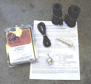
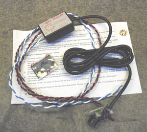
The Heat-Troller kit came with the controller including the remote control (a rheostat with ‘off’ detente full counter-clockwise) and indicator LED. There is plenty of wire for locating the controller and the switch on different parts of the bike and lots of wire for between the controller and the grips themselves. Also included is a hook and loop set for mounting the controller and an extra sleeve nut for the remote control in case some extra thickness is encountered in your mounting location. If you want the grips to turn on and off with the ignition switch (a really good idea), you need to get a simple 12v relay. I got one from Radio Shack (cat number 275-226) for $6.50 and this is a standard stocking item (as of 2011, anyway). Any self-respecting Radio Shack will have one. The advantage of the controller over the included off-med-high switch is more precise temperature control and power savings. In the case of the two-position switch, excess power is wasted heating a resistor while the Heat-Troller cycles power to the grips thus saving power. This might be important if you have a bunch of other electrical equipment vying for limited power on the bike.
To install the grips, first I removed the existing grips. I was able to get them off without cutting them but it was a struggle. Cutting them would have been a lot easier but then I would have been stuck if I had a problem getting the HOT Grips on. The stock grips are not glued or otherwise held in place with anything other than their own grippy selves.
I started with the throttle side and dry-fit the grip to see what I needed to do to make it work. The throttle tube is ribbed and has ridges on the end. To get the Hot Grip on you have to remove the end ridges and at least half of the ribs that run the length of the bar. This was pretty easy to do with a Dremel rotary tool with a course sanding drum.
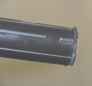
I only took off half of the length-wise ribs from one side of the tube and the grip fit nicely. I don’t notice any effects from the eccentricity error.
I also found that the Hot Grip itself needed to have a small amount of material removed from the bar-weight end to fit on the tube. It was a simple task to just grind out some of the grip (using the Dremel again – you gotta have on of these things and this a good excuse to get one if you don’t).
The left grip went on without any adjustments needed except for the outside end which, like the other side, did need a little material removed to fit easily. They warn you not to try to stretch the grips to make them fit as this will likely damage the heat elements.
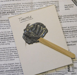
Following the Hot Grip instructions (which are quite good), the next step is to determine where the cable should come out of the grip. This is especially important on the throttle side since there has to be some free play of the cable to allow the throttle to move. The Sprint’s throttle covers 90 degrees from fully closed to fully open. I have them marked in the photo. Use these marks to make sure the grip goes on in the right place once you have the epoxy on the throttle tube.
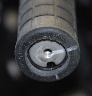
Note that in the picture the grip is not all the way on the throttle tube – this was before I cleaned out the grip end a little more so it would fit easily all the way up the tube. Once I had done that the grip was flush with the end of the bar and throttle tube.
Once I had the grips dry fit on the tubes I mixed up the epoxy and put the grips on. I like to mix epoxy on a small pad of paper (if it isn’t too viscous – JB Weld is perfect this way) because you can just remove the top sheet and you have fresh mixing surface. I also write down the location where I am using the mixed epoxy if I am doing multiple batches. That way, if a mix doesn’t set properly or has some other problem, I know where to look for trouble on my project. The epoxy left on the mixing surface is allowed to cure and then I test it to make sure it did what it was supposed to. It also gives me a handy indication of when it has cured.
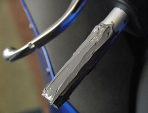
The photo above is the left bar with the JB Weld already in place. The throttle side was just as easy. I left a half inch or so uncovered on the inside of the bar so that epoxy could be pushed up and not make a mess between the grip and the control housing. This is especially important on the throttle side.
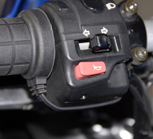
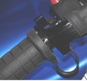
The only thing left to do for the physical installation is to wait for the epoxy to cure and route the cables from the grips to where the controller will be. I had some thin black cable ties that I used to secure the throttle side cable to the bar close to the throttle control housing. On the other side a single cable tie was all I needed to make the cable lie neatly under the switch housing. From there, both wires followed existing cables down into the bowels of the bike.
With the grips installed, I moved on to the electrical installation….
I decided that I wanted the control to be in the instrument panel. I don’t like the OEM switch position which is out on the infill panel. It is a long way to reach when you need to adjust the grip temperature. Also, the cable would be in the way when removing the infill panel which, on the Sprint, is any time that you want to remove the side panels. So I mounted the switch in the space below the three trip computer switches.
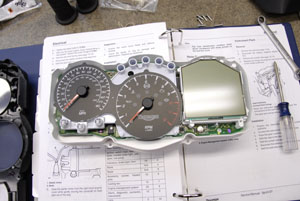
Remove the instrument panel by removing the windshield and then the two clips that hold the panel to the bike. There is also a cable bundle that goes to the panel that is connected under a gray boot. It’s pretty easy.
The instrument panel comes apart just as easily – 8 screws and it separates from the front bezel.
The Heat-Troller switch can be separated from the LED by snapping the circuit board along the scored line. This gives the LED a couple of inches of freedom allowing more flexible mounting options for both the switch and the LED. The switch is connected to the controller with a multi-conductor cable. It can be mounted just about anywhere in the cockpit with plenty of cable to place the controller just about anyplace else on the bike.
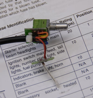
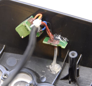
The left image (above) shows the switch and LED boards separated. The LED has one lead insulated so you don’t have to worry much about the “legs” getting crossed. The photo on the right shows the switch mounted in the lower part of the panel and the LED hot glued just under the switch holes on the top part of the panel (the panel is upside down in this photo.) I also hot glued the LED board to the panel to prevent it from vibrating. Hot glue is great for this application because it is flexible, waterproof and fast. (Update – after almost 9 years it is still in perfect condition.)
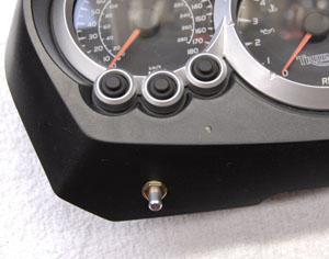
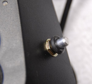
The left photo shows the switch and LED mounted in the panel. The LED is almost invisible. The right photo shows the grommet that comes with the Heat-Troller. The grommet goes under the knob to help seal the switch and give it some extra turning friction to prevent accidental operation.
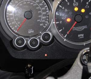
In the photo above, this is how the panel looks once it is installed and operating. The switch is easy to get to from the riding position and the LED is very easy to see.
Now the electrical hook up: The first decision is physically where to put the control box for the Heat-Troller. On the Sprint, the space under the windshield is perfect. There is a lot of room there with almost nothing else in there and it is easy to get to and work in. The controller and the relay that controls power to it will go there, too.
Route the wires from the grips up to the space behind the instrument panel. Route three wires down to the OEM heated grip connector (under the left headlight). The OEM connector has three wires leading to it:
– Purple: This is power from fuse number 6 for the grips
– Black: This is ground
– Blue/Red: This is the signal from the ignition that turns on the relay that feeds power to the controller
Here is the section of the bike’s schematic that shows what is in the bike (stock):
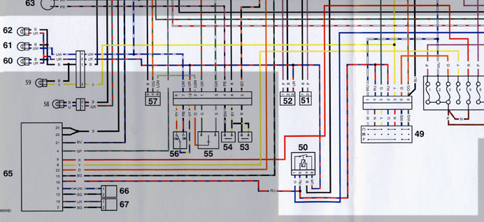
The grayed out portions are not important for this project. 60 and 62 are the two “dipped beam” headlights. 52 is the OEM heated grip connector. 50 is the headlight relay. This relay is turned on when the ignition switch (49) is in the “run” position and turned off when the starter is initiated (so the headlights turn off when you are cranking the engine). The fuse box is at far right. The wire colors are “P” for purple, “B” for black and “UR” for Blue/Red. Purple is the power source (fuse #6), Blue/Red is the relay control signal, and Black goes to ground.
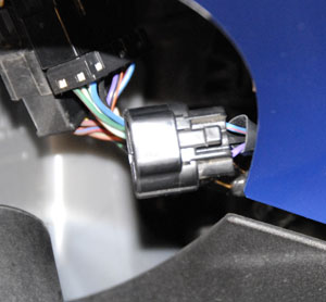
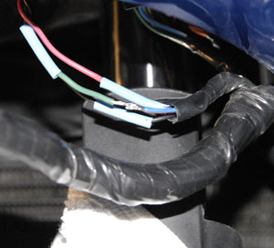
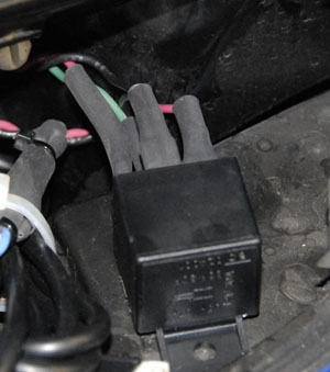
The OEM connector for the grips is located under the left headlight. In the picture above you can see the color of the wires running into the back of the connector. The mating part of the connector has no contacts in it so it is not possible to use the connector as is. I didn’t want to try to track down the connector and get a male side or the contact inserts so I cut the wires and spliced my wires to them.
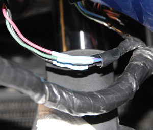
The right photo shows the Blue/Red wire connected to a green wire, soldered with a basic butt joint. I used heat shrink tubing to cover each of the connections. The right photo shows the heat shrink tube after shrinking. The wire harness in the photo comes out from behind the front plastic part that contains the headlights. This whole mess is just above the front wheel.
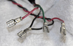
 Next, behind the instrument panel, I connected the wires from the grips to the Blue and White wires coming out of the Heat-Troller’s control box. I also soldered connectors onto the ends of the power supply wires (Red and Black) and the three wires coming up from the wiring harness. I don’t like having two red wires in the same place with different functions so I wrapped one with yellow tape to tell it apart from the other. (I hadn’t done that yet in the photo above.)
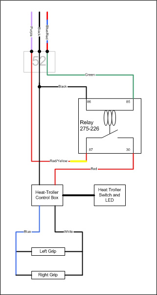
The Radio Shack relay has four connections with numbers that were picked at random or have meaning that is beyond my level of understanding:
#86 – This is one side of the actuating solenoid. I attached both black wires to this. They come from the power input side of the Heat-Troller control box and from the ground wire in the harness (used to be in the OEM heated grips connector that I cut out in the prior step.)
#85 – This is the other side other actuating solenoid. This hooks up with the red wire that came from the Blue/Red wire in the wiring harness.
#87 – This is the first side of the switched circuit. The red (with yellow tape) wire from the harness’ Purple wire connects here.
#30 – (WHY 30? I don’t get why it isn’t #88 or #84….) This is the other side of the switched circuit and connected to the Red wire from the Heat-Troller control box.
The schematic to the left is the finished circuit.
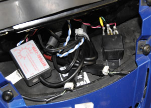
The Heat-Troller control box was velcroed on the right side and the relay on the left. The finished installation is shown below. Well, almost finished – I put some heat shrink tubing over the connectors on the relay to protect them from… dust. It doesn’t do much but it makes me feel like it will hold up better. The only thing left was to dress all the wires so they wouldn’t get chewed up, tangled, or otherwise out of sorts.
Impressions of the Grips and the Heat-Troller
I’ve been riding around with the grips for a couple weeks now and I like them a lot. They get nice a toasty in a hurry when the bike is running -not so fast when it isn’t. Probably due to a lower voltage going to the grips. They are only slightly bigger around (it is noticeable) and “sticky” so my leather gloves and plastic rain glove covers don’t slide on them at all. The positioning of the control knob is good – easily managed when stopped. I don’t think I would try to adjust it while at speed.
The LED is really easy to see. It is a little distracting at first because it blinks at the rate that the controller is feeding power to the grips (or relatively so.) So at low temps it blinks on less than it is off. At higher temps it is on more than off and at full tilt it is on almost all the time. I don’t know why but flashing red lights are not easy to get used to on a bike.
I am very happy that I took the time to install the relay. It would be easier to install this without it but you would have to remember to turn the grips off each time you shut off the bike. I know I would forget and kill my battery. The extra time and effort are worth not having to think.
Heated Grip – First Winter’s Impressions (Feb 2007)
The value of warm hands cannot be over estimated. The grips have been operating now for several months and have gotten me through a rather difficult winter here in the Pacific Northwest. When it rains the grips are dry. When it is cold my hands stay warm in my regular lined leather gloves. The grips are plenty “sticky” so that I never feel like I don’t have enough grip even in plastic rain over-gloves. The grips are well worth the effort and expense.
The Heat-Troller is a nice addition. The grips would be too hot at full power and probably not quite warm enough at the mid setting that an off-mid-full switch arrangement would offer. The variable setting capability is worth the extra cost and complexity. I can change it on the fly (though I don’t usually when I’m moving) and the red LED indicator has stopped annoying me now that I am used to it.
Setting it up to turn on and off with the ignition completely takes the issue of running down the battery away and is worth the extra time and expense it takes to make it happen. I don’t even think about the grips anymore – they are just there and keep my hands warm.
All in all, I would do this again and will never have another bike without heated grips.
The value of warm hands cannot be over estimated.
Or, Planned For (Update 2011)
Over last summer I took a trip up North to Canada (I live in the Seattle area) and in one day I went from hot (near 100 degrees F), to cold (less than 50 degrees F). My riding suite (a ‘Stich – another story) kept me cool and warm (a miracle) and my grips made it so my hands worked going over the passes. Warm hands in the summer may not be a problem where you are but it pays to be ready!
2015 Update – Still Warm
Yeah, still have the bike, still have warm hands. A great value.
2020 and Nothing Changes
The bike and the grips keep on keepin’ on.